


Universal Flash Storage (UFS) is a flash storage specification aimed at providing high performance and low power storage memory for mobile phones. UFS has been supported in the Linux kernel since v3.4. Specifications for UFS and its associated Host Controller Interface (UFSHCI) are maintained by the JEDEC standards committee. Specifications like these are periodically updated to meet industry needs. The JEDEC committee has recently released v4.0 of the UFS and UFSHCI specifications, improving the performance and data protection of UFS based systems.
One of the key performance features added to the UFSHCI specification is Multi-Circular Queue (MCQ) support that allows each CPU core to handle data transfer simultaneously to boost performance of multi-core systems. Qualcomm Technologies, Inc developers Asutosh Das and Can Guo have recently submitted a series of patches adding MCQ support to the UFS subsystem in Linux Kernel, which Linaro helped review, and the patches were merged for v6.3 kernel release. The rest of this article discusses the internals of MCQ support and how it is implemented in the Linux kernel.
Documentation available in the kernel source tree provides an architectural overview of UFS. This article focuses on UFSHCI, where MCQ support is added.
UFSHCI
The UFSHCI specification defines an interface for a device driver to access a UFS host controller in a standard way. This allows a generic driver to manage UFS Host Controllers (HCIs) from different hardware vendors.
The HCI driver communicates with a UFS device through a set of memory-mapped I/O (MMIO) registers in the host controller, and transfer descriptors in host memory. The transfer descriptors are data structures organized in the form of transfer “lists” in host memory. The host controller accesses these lists and submits commands to the UFS device in the form of UFS Protocol Information Unit (UPIU). When a response is received from the device in the form of UPIU, the host controller passes the response to the driver using transfer lists.
Data transfer
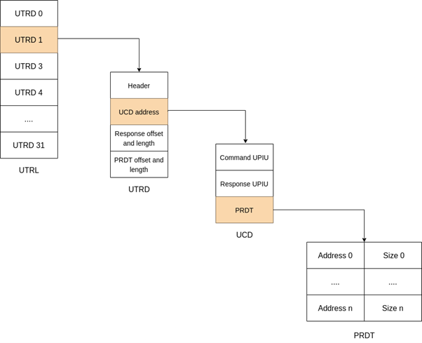
The data transfer between the HCI driver and the UFS device happens through an array of data structures called UTP Transfer Request Descriptors (UTRD). These descriptors are contained in a list called UTP Transfer Request List (UTRL) in host memory. A descriptor contains the information required for the host controller to create the command UPIU to be sent to the device and also to pass the response from the device received over response UPIU. The data associated with both command and response UPIUs are transferred using the Physical Region Description Table (PRDT) which consists of an array of pointer and size of data buffers.
The UTRL has a doorbell register associated with it, which indicates which UTRDs are available for processing. When the HCI driver writes (rings) to the doorbell register, the controller is signaled of a new work item added to the list. And when the host controller has received the response from the device, it generates an interrupt that allows the HCI driver to handle the completion.
UFS supports a subset of SCSI commands and uses them to communicate with the device. Each SCSI command is identified using a unique task tag, an identifier defined by SCSI. To service a SCSI request, the HCI driver prepares a UTRD, places it on the UTRL and rings the doorbell indicating to the host controller that the UTRD is ready for processing. The host controller parses the UTRDs in the order they were placed on the list and issues the commands to UFS device. On receiving the response from the device, controller updates the response UPIU fields of the corresponding UTRD on the list and notifies the HCI driver through interrupt if applicable. The host controller and driver make use of the task tag to identify the UTRDs in the list.
In response to the interrupt, the HCI driver reads the UTRL doorbell register and compares the value to the list of commands that have been submitted by the driver and not yet completed. Finally, it completes the commands that are outstanding and makes room for the successive commands in the list.
UFS Legacy Single Doorbell (SDB) mode
Prior to UFSHCI specification v4.0, Single Doorbell (SDB) mode was used for data transfer by the HCI driver. In SDB mode, a single UTRL in host memory and a doorbell register in the controller’s MMIO space are used to perform SCSI tasks. The use of a single transfer list becomes a bottleneck in multi-core systems where each CPU core may try to submit transfer requests simultaneously. Additionally, with only 32 UTRDs available, the list can run out of UTRDs quickly, and in that case new requests must wait for a response from the device to get a free UTRD.
UFSHCI v4.0 introduced Multi-Circular Queue (MCQ) support to overcome this performance bottleneck.
UFS MCQ mode
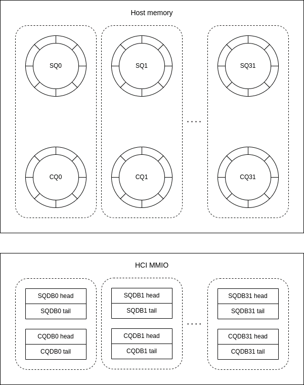
UFS MCQ mode employs a model similar to SDB mode, but it allows multiple “queues” (rather than a single “list”), and each queue supports an implementation-defined number of elements (rather than the 32 used for SDB mode). In addition, separate queues are used to represent submitted and completed commands; this is similar to what is used for NVMe. The use of multiple queues allows more than one CPU in a multi-core system to take control of a queue concurrently, thereby reducing the single-list bottleneck found in SDB mode. Up to 32 submission queues and 32 completion queues are allowed by UFSHCI in MCQ mode; the number of each is implementation-defined.
The queues are circular, in that the head pointer in a queue always refers to the next free (or unused) entry in the queue and the tail pointer always refers to the last in-use entry. As the head and tail pointers advance, they wrap to the beginning when they reach the end. When the head and tail pointers are equal, the queue is considered to be empty. When they are not equal, the queue contains one or more entries.
MCQ mode comprises 3 major components:
- Submission Queue (SQ)
- Completion Queue (CQ)
- Doorbell (DB)
Submission Queue (SQ)
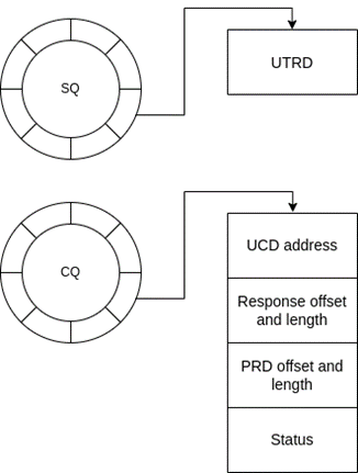
An SQ is implemented as a circular queue of UTRDs, where the HCI driver is the producer and the host controller is the consumer. The HCI driver submits the commands to the host controller by adding UTRDs to the SQ and increments the doorbell tail pointer associated with it. Each SQ is mapped to a Completion Queue (CQ) through which it receives the command completion notification from the host controller. A CQ can be shared by multiple SQs, but the MCQ support added only supports a 1:1 mapping between an SQ and a CQ.
Completion Queue (CQ)
A CQ is also implemented as a circular queue, where the host controller is the producer and the HCI driver is the consumer. After receiving the response UPIU from the device, the host controller updates the relevant head entry of the CQ and raises the interrupt to the HCI driver. The content of the CQ entries looks similar to the UTRDs but they vary slightly by the addition of ID corresponding to the SQ and the Overall Command Status (OCS) field.
Doorbell (DB)
UFSHCI defines separate doorbell registers for each of the SQ and CQ in the host controller’s MMIO region. The doorbell registers are used to pass the head and tail pointers (offsets) of the SQ and CQ between the host controller and the driver. The doorbell registers associated with the SQ are also used to signal notifications by the driver to the host controller for processing the SQs.
MCQ implementation in Linux Kernel
Upon receiving a SCSI request, the HCI driver determines the SQ to which the request should be queued, prepares a UTRD and writes it to an entry corresponding to the current doorbell tail pointer of the SQ. Then, it increments the doorbell tail pointer to indicate that it has consumed this entry. This generates a doorbell notification to the host controller.
On receiving the doorbell notification, the host controller fetches the entry from SQ and increments the doorbell head pointer indicating that the entry is free for consumption. It prepares the command UPIU based on the SQ entry and sends it to the device. The device will process the UPIU and when the transfer is complete, it sends a response UPIU back.
After receiving the response from the device, the host controller updates the entry corresponding to the current doorbell tail pointer of the CQ associated with the SQ. The updated entry includes response UPIU, command status, and the SQ ID. Then the host controller increments the doorbell tail pointer, indicating that it has produced (filled) another entry. This causes an interrupt to the CPU, which will be serviced by the driver.
On receiving the interrupt, the driver reads the Interrupt Status register (CQIS) to find out which CQ has generated the interrupt. After finding out the CQ, the driver looks for the task tag associated with the CQ entry.
Currently, the driver uses only shared task tags across all of the SQ/CQ queues i.e., the SCSI layer will use the same set of task tags for each of the queues supported by the host controller. Using shared task tags simplifies the MCQ implementation, but on the other hand, the per-queue task tags may also give performance boost.
Finally, the completion of the relevant SCSI request associated with the task tag is processed by the driver and it increments the doorbell head pointer of the CQ.
Conclusion
The MCQ support has been verified on Qualcomm and MediaTek SoCs. Although it is reported that the MCQ series brings performance improvements to the UFS subsystem, there are no performance metrics available from the vendors at this time. The MCQ support added is an initial one and further improvements are possible, including:
- Adding CPU affinity to the queues (SQ and CQ)
- Using per-queue task tags
- Mapping multiple SQs to a single CQ (N:1)
For more information about what Qualcomm platform services Linaro offers and how we can help develop, maintain and optimize products using Qualcomm technologies, go to https://www.linaro.org/services/qualcomm-platforms-services/.