


A step-by-step guide to the Armv9 boot sequence and EBBR
The boot sequence on Arm-based embedded systems is nuanced and complex, and has evolved a great deal since early mobile devices in the mid-to-late ‘90s began to leverage Arm CPUs for their unparalleled power efficiency. Since then, the prevalence of the Arm architecture has grown to span many industries, each with their own unique sets of challenges and requirements around security, compatibility and feature set.
While many silicon vendors and board integrators continue to implement their own “secret sauce” when it comes to firmware and bootloaders, the industry has gradually been moving closer to more generic, unified solutions, primarily to greatly improve reuse, reliability and reduce maintenance burden. This article will focus on booting on an Armv9 SoC, using the Trusted-Firmware A project for secure monitor firmware, U-Boot as the bootloader and Linux as the OS.
Powering Up…
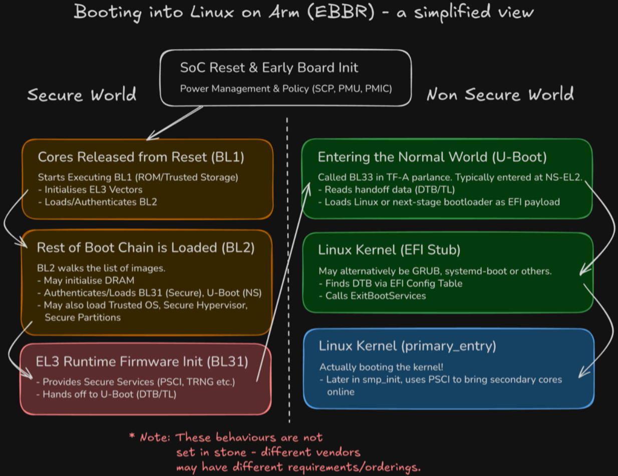
Once board power is applied, and the System Control Processor (SCP) or simpler platform-specific PMIC is ready to power and clock a cluster, it will be released from reset. At this point, all powered cores will begin executing from the address described by RVBAR_EL3, typically static and set by the hardware. All but one will branch into some form of “holding pen” where they will spin (or wait for interrupt) until firmware decides to admit them into the boot process. This is where we enter Trusted Firmware’s BL1 binary, resident in trusted, immutable storage. This is typically stored in literal mask ROM in the SoC itself, in one-time programmable ROM or some trusted area of NOR flash.
It is here where minimal initialisation is performed to load and run the next stage of boot. Some common actions here are preparing SRAM, initialising EL3’s exception vectors, enabling the instruction cache, initialising SCR_EL3 and SCTLR_EL3 and setting up an early console to debug early failures. The “next stage of boot” is, in our model, TF-A BL2, but may in fact be a binary such as U-Boot SPL or another vendor-specific blob. The main role of this stage is to authenticate and load the other binaries, including the eventual bootloader.
Loading the Bootloader
BL2 acts as the “gatekeeper” to the rest of the boot process, by authenticating all downstream images and loading them at their respective addresses. At this point, we likely also need to train and initialise DRAM if our board has it and it wasn’t done earlier by hardware. While components such as the Trusted OS and EL3 Runtime Firmware will be loaded into Secure memory, our BL33 payload (U-Boot) will be loaded into Non-Secure memory. For now, we will assume we don’t have a Trusted OS, as we are more interested in getting to Linux!
The EL3 Runtime Firmware
Once all images are loaded by BL2, it makes a secure monitor call (SMC) back to BL1 which transfers control to BL31, also known as the EL3 runtime firmware or secure monitor firmware. As the name suggests, this offers a “runtime” which remains accessible for the lifetime of the system, providing secure services such as PSCI (for power state coordination - where Linux can ask to bring cores online/offline) and access to interfaces for communication with secure partitions, such as to offer DRM and secure storage services. If we have a Trusted OS (e.g. OP-TEE) or Trusted Hypervisor (e.g. Hafnium) payload, control would now be handed off to that. For now, let’s look at the handoff to U-Boot.
Handoff to U-Boot
Firmware handoff has been a topic of investigation within Linaro’s LEDGE group over the last couple of years. There are currently 2 options:
- Simply passing the base address of the DTB (DeviceTree) in either register x0 or x1, similar to what Linux expects.
- Using a Transfer List, a structure that was designed to be easier to process than DeviceTree, specifically for the firmware handoff use-case. You can read more about Transfer Lists at Raymond Mao’s excellent blog post. The TL Is a structure that persists in memory and provides data not only for BL33 but for other boot stages, too. Notably, BL31 needs to move the TL to non-secure memory so that U-Boot can read it, before hand-off. In this case, U-Boot receives a magic number in x1 so it can identify it has been handed a TL, as well as the base address and length of the TL. Within the TL, and entry contains the address of the DTB in memory.
One of these 2 approaches is used depending on build options, and the appropriate context and world switch is performed to enter BL33 at (typically) NS-EL2.
What is EBBR anyway?
Now we are in the bootloader, looking to boot the OS, we need to understand what the OS expects. Arm defines a set of “recipes” for what they call “Base Boot Requirements” (BBR). These define the boot procedure and services that the OS/hypervisor can expect to be available. There are currently 2 SystemReady bands, “SystemReady” and “SystemReady DeviceTree”. For our embedded use-case, we will concentrate on the latter, which mandates use of the “Embedded Base Boot Requirements” recipe. U-Boot provides a minimal UEFI implementation capable of loading an EFI executable, provided by CONFIG_EFI_LOADER. A common misconception is that booting using UEFI mandates ACPI. In fact, with EBBR, continuing to pass a DeviceTree to the EFI payload is still by far the most common choice. When booting the EFI payload, which may be loaded as usual by any of U-Boot’s block device commands, U-Boot installs a special EFI_DTB_TABLE_GUIDentry into the EFI Configuration Table, describing where the DTB lives. Downstream bootloaders, such as GRUB, systemd-boot or the Linux EFI stub itself then finds the DeviceTree by scanning the System Table.
Inside the Linux kernel
Fun fact: The Linux kernel can masquerade as a PE/COFF executable and therefore can be treated as an EFI binary. So, it is called (either directly from U-Boot, or from another bootloader stage) using the standard (ImageHandle, SystemTable) argument pair in x0, x1. Linux then navigates the Configuration Table as before. The EFI stub then performs the final handoff, allocates a new FDT with EFI reserved memory described, calls ExitBootServices to nullify the boot services pointer and switch to post-boot runtime services, before calling into regular primary_entrywith the aforementioned FDT pointer. The kernel then has to do quite a bit of initialisation (setup scheduler, init driver model, etc.) before it is time to bring the secondary cores online (up) using PSCI in smp_init().
Further Reading and Follow-up
That was a whistlestop tour of booting an embedded Arm system. I have skipped many details around security hardening/mitigations, subsystems and services, realms and “confidential compute,” and other bootloaders such as EDK2. There is much more to learn and many moving parts. To learn more about these topics, consider exploring Linaro’s training options, including:
- Arm Linux Kernel Development
- Advanced Linux Kernel Debugging
- Introduction to Trusted Firmware-A
- Introduction to OP-TEE
Also, consider reading our other great blog posts for information on Confidential Compute Architecture (CCA) and Realm management.
Register for the next training course here.